3D modeling of the nerves of the left upper limb - Materials and Methods
3D Vector Reconstruction of
Korean Visible Human
Left Upper Extremity Nerves
Materials and methods
Body selection
The body chosen in our study was selected from all cadavers donated to science for medical research with the consent of their relatives [4]. Consent had also been given in cases of prisoners who died by lethal injections.
The subject was chosen to be as representative as possible of the population, in this case the Korean population. The subject selected was a man who died at the age of 33 on 26 March 2001 of leukemia, and his body therefore bore the sequelae of leukemia: he had splenomegaly, pneumopathy and adenopathy [4].
He was 1.64 m tall and weighed 55 kg.
MRI and CT scan
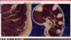
For all the Visible Human Project (VHP), the main data are the images obtained by cryomatocromes with their true human colors; as well as MRIs and scans of the same cadavers as complements. The MRIs and scans are useful because they make it easy to find the different structures, especially for doctors and medical students used to this image format.
For KVH, however, cadaver MRI was not of the same quality as live MRI.
The cadaver was scanned in its entirety by MRI, then scanned every 1.0 mm and completely sectioned in 0.2-mm slices. The cadaver was explored with a Philips Brillance 64-slice scanner.
Preparation of the cadaver:
In Korea, the cadavers were not injected with fixatives or dyes. The sections therefore retained the original colors of a living human body. In contrast, in the United States and China, fixatives were injected into the arteries of the cadavers in order to obtain more precise contours in the images. In China, after the injection of the fixative, an injection of red dye was performed, which was very useful to identify the different arterial branches from one slice to another. These different preparations allowed images of varying quality and therefore different data to be made available to users.
The posture of the male VHP cadaver was such that the palms of his hands were facing his trunk, making it difficult to identify the hand structures in a horizontal plane. Thus, in Korea and China, the palms were placed on either side of the trunk, relatively close to the anatomical reference position.
The cadavers have all the dorsal parts of their bodies more or less flattened due to their supine positions when they died. After freezing the cadavers, their backs were irreversibly flattened in the images and 3D models. VCH was the only project to resolve this artifact by going through a massage and embalming protocol with the cadaver in an upright position.
Photographs of anatomical sections:
In the VHP, the researchers had no choice but to cut the cadaver into four pieces due to the limitations of the size of the embalming machines and
of the cryomatocrome. As a result, inevitable losses between the four parts occurred, resulting in incomplete data. In Korea and China, these imperfections were avoided by making the material large enough to hold a whole human body.
For the KVH, a very large laboratory was necessary for the use of equipment such as: the cryomatocrome (5mx4mx3m), photographic instruments, light installations or computers. This large space was beneficial during the cutting and photographic procedures, allowing the obtaining of high quality images.
In addition, another constraint was imposed, the laboratory had to be sufficiently cold (around 0°C) in order to prevent the frozen embalming "boxes" from melting during the sections, which was very difficult to maintain at the right temperature. The cuts were thus made in winter, with the windows open. At best, a hundred cuts could be made each day.
Cutting segmentation:
The slice intervals for the cadavers were approximately 0.2 mm. The fact that the size was the same for an interval and a pixel allowed sophisticated volume reconstructions to be obtained due to the fact that voxels of 0.2 mm edge size were obtained. Subsequently, voxels of 0.1mm were obtained for the heads and pelvis of a cadaver and the body of a child. A future attempt could be to obtain 0.1 mm voxels for a whole adult body.
Despite very accurate testing of cuts and photography, there were misalignments and changes in brightness between successive cuts. The misalignments and brightness problems were detected using marker rods and gray scales, respectively.
Winsurf software
Presentation of the Winsurf software
Winsurf is the PC version of Surfdriver (software designed to model quickly and reliably sectioned biological material). It is a more recent version of the latter usable by all, professionals or individuals
It dates from 2007, but has the advantage of being easy to use and free.
Objects in images are identified by placing points along the edge of the object, thus defining its "contour". Some tools facilitate the placement of these contours, such as the "magic wand" which, on segmented sections, automatically surrounds an object that has been colored beforehand.
Once the contours are all done on the set of selected images, the different points of each contour are connected through a "routine" used by the software. This routine finds the best solution to join the different vertices of each consecutive image, using a point density defined beforehand by the user.
The objects, now made, are rendered in the second part of the software, where you can then work on the lighting and the colors. Several objects can be loaded at the same time and Winsurf automatically places them in the right alignment with each other.
A last characteristic can be worked on: the ability to make an object more or less smooth, by reducing or removing the different angles created by vertices that would be too far apart. This function (the "smooth") allows to obtain a sharper, more beautiful object. But in the modeling of the nerves of the left upper limb, the result was not convincing, so this function was not used.
Functions of the software
From a more technical point of view the software has two interfaces:
- the 2D interface
- and the 3D interface.
The 2D interface
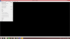
The 2D part is the one that allows you to work on the cuts. It is composed of several tools that can be found on the bar on the left of the screen.
- Thefirst one allows to go to the 3D mode, detailed below.
- The2nd one allows to adjust the contours (not much used).
- Thethird one, the "magic wand", allows to save a lot of time on segmented cuts, one "click" is enough to make the contours of a whole object, the contour is automatic.
- The4th, "straight line", allows the user to make points one by one on the object to "contour" it. The x and y coordinates are recorded at each point, while the z coordinate changes when moving to another cut.
- The 5th one, the "pencil", allows the user to surround his object with a continuous line, and it is the WinSurf software that will place points along the path, the number of points will depend on the density (itself defined in a window that can be opened with a right click).
- The 6th one allows to "zoom in" and "zoom out".
- The 7th, the "hand", allows you to move each point individually after the plot.
- The 8th one allows you to add points to a plot.
- The 9th, the "eraser", deletes one or more points of a plot.
- The last one, which is not used much either, allows you to place markers on different cuts.
The 3D interface
The 3D part allows to work on the reconstructed models. It also contains several tools.
- The1st one allows to go back to the 2D mode.
- The2nd one allows you to go to the adjustment window which we will talk about later.
- The3rd hand allows to move the object in the window.
- The4th one allows to "zoom in" and "zoom out" by moving along the Z axis.
- The 5th (the "trackball") allows you to switch to a top or bottom view.
- The 6th one allows to turn the object according to a Y axis.
- The 7th one allows to turn the object along an X axis.
- The 8th one allows to turn the object along the Z axis.
- The 9th allows you to go to the texture window. In this one we can: change the color of the object via an RGB system (Red Green Blue), make the object visible or not (visible), apply a lighting or not (lighting), depict the object in order to make it a model without surface, apply or not the textures, display each color of contour used for the object, Smooth object allows to smooth the object, the object shrinking in function. You can choose the opacity and the brightness of the object. Finally you can apply textures to the objects.
- The 10th allows you to take a picture of the 3D window.
- The "measure" tool allows to measure the distance between two points using the measuring system entered in the cut characteristics.
- The 12th ("toggle marker") allows you to add or remove a marker from the window
Finally in the 3D view, the bar tools at the top of the program also have some use.
In the "Tools" tab, you can change the background color and take a video of the program window. The "Advanced" tab offers three possibilities. In "Advanced surfacing" you can choose the output of the program. "Proof" allows a fast output but with a low quality, "Best" allows a higher output but will induce a slowness in the display of the object. The " slice locator " tool allows you to reach the 2D slice corresponding to a region of the 3D object (just click somewhere on the 3D object).
Practical use of Winsurf
In order to create a 3D model on Winsurf, you must first click on "new contour file" in the "file" tab. A window will then open allowing us to choose the image base that will be used as a cut. Once this is done, you must choose the width, thickness and interval between each cut.
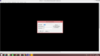
In our project, the width was 5650, the thickness was 2 and the interval depended on the anatomical part considered (the more precise a part was, the smaller the interval between each cut had to be, and vice versa). Then, on the 2D window, we are allowed to "contour" our slices one by one. We must always contour the elements in the same direction, starting if possible at the same place, and using the same point density from one cut to the next. If these conditions are not respected, the rendering will not be of good quality.
Once the contours of our element are made on each of the cuts, we must not forget to "clap" the objects, so that the ends are closed.
In the case where we want to represent an object that divides (a vessel for example), we can use different channels.
We can then go to the 3D section, where we can work on the three-dimensional object using the tools detailed above. For example, we can smooth the object, define its color or give it a certain texture.
Characteristics and data used for modeling
The objective of the study being to model in 3D the different nerves of the left upper limb from the anatomical sections of the Korean Visible Human (KVH), we have therefore carried out for each nerve the operating procedure of the Winsurf software described above.
Only the sections numbered 1711 to 4541 (i.e. 2830 sections of the left upper limb) were used for our study, with the following characteristics:
- the width was 5650, the thickness 2 and the interval depends on the anatomical part considered (on average 10)
- for the nerves: the color references (Red/Blue/green system) were 180/70/60 with a shininess of 30;
Screenshots of the different 3D models were then taken to show the results.
Marie Messager
Osteopath in Versailles Chantiers
78 - Yvelines